
3.18UPS Panel (Generic)
A read-only full-screen UPS page where you map each readout to a UPS Manager value or any Modbus datapoint, for single-phase or three-phase output.
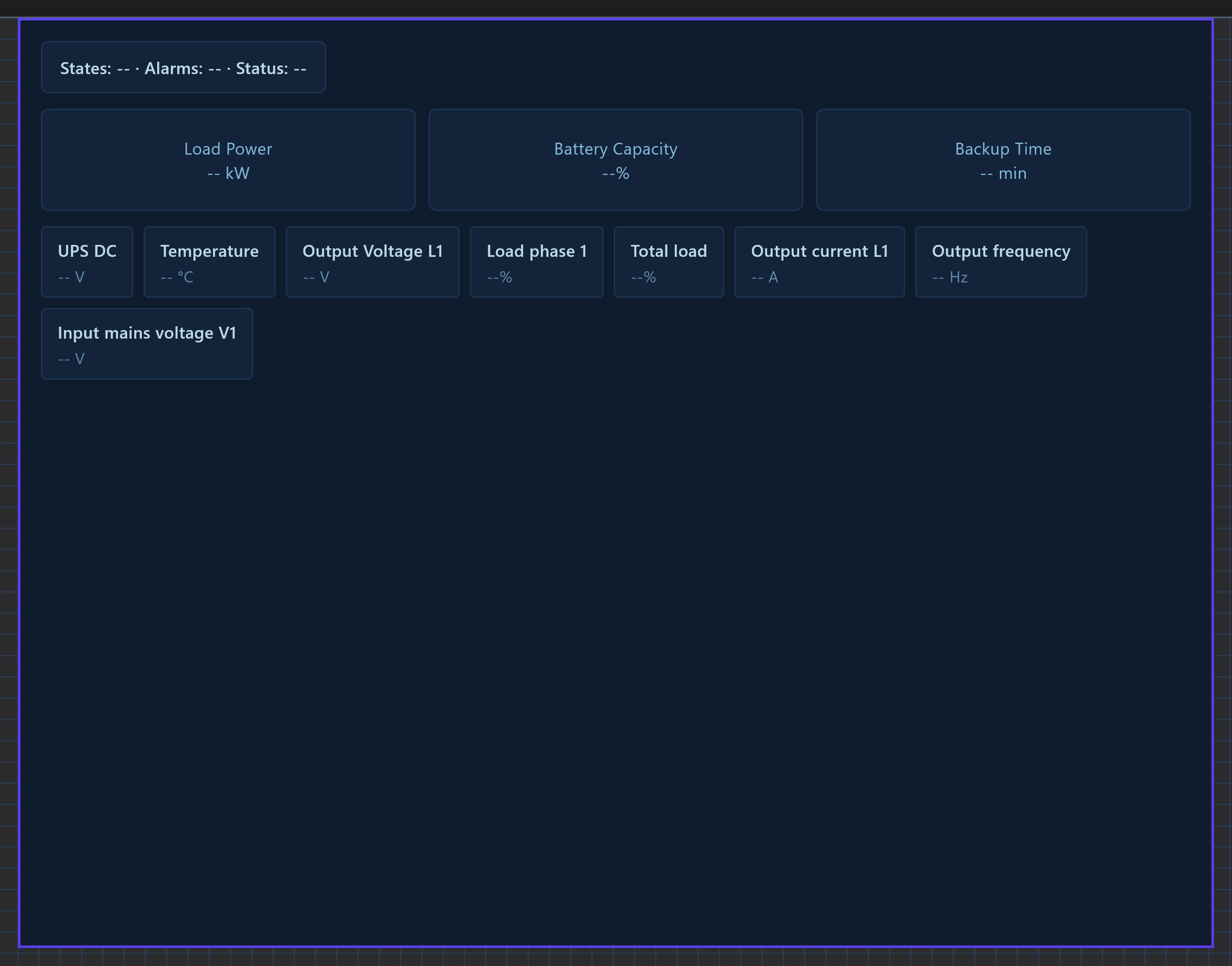
The generic UPS panel shows the state, load, battery and mains figures of a UPS. You choose the source of every readout yourself, so it works with the Socomec UPS driver and with any other UPS that you read through Modbus datapoints. It has no buttons: it is a display only.
#When to use it
Use it when the UPS is not a Socomec Netys, Itys or Masterys, when it has a three-phase output, or when you want only some readouts. If you have a Socomec UPS and want the buzzer and test buttons, use the UPS Panel. Put the panel alone on its own page: in the apps it fills the whole screen.
#What you need first
Each field needs a source, either of:
- the UPS Manager (Server > Internal services > UPS Manager, with its Modbus RTU Device selected, for a Socomec UPS), or
- a Modbus datapoint added under Configure RTU Devices on the RS485 or RS232 interface. See Modbus devices and datapoints.
A source appears in the drop-downs only after it exists in the project.
#Properties
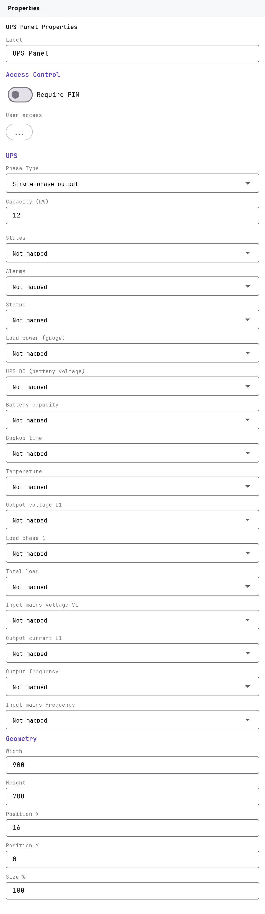
The Label, Access Control, Width, Height, Position X, Position Y and Size % fields work as described in Common properties. The Label is only a name in the Configurator (its default is UPS Panel). Default size is 900 by 700, used for the editor preview only. There is no Text Style or Protocol field.
| Property | What it does |
|---|---|
| Phase Type | Single-phase output (default) or Three-phase output. Three-phase adds the L2 and L3 rows below and shows them in the apps. |
| Capacity (kW) | 0.5 to 5000, default 12. The full scale of the Load Power gauge. |
| Auto-map to UPS Manager | A button, shown only once the UPS Manager has a Modbus RTU Device. It fills 14 of the fields from the manager and leaves Status and every L2 and L3 field empty. |
#Field mapping
Every row is a drop-down with the placeholder Not mapped, with a clear button. It has a UPS Manager group (when configured) and a Modbus RTU group (every datapoint, shown as device - datapoint).
| Property | What it shows in the apps |
|---|---|
| States | Text in the States box (for example On Mains). |
| Alarms | Text in the Alarms box. |
| Status | Text in the Status box. The UPS Manager has no value for it. |
| Load power (gauge) | The Load Power gauge in kW, from 0 to Capacity (kW). |
| UPS DC (battery voltage) | UPS DC in volts. |
| Battery capacity | The Battery Capacity gauge, 0 to 100 percent. |
| Backup time | Backup Time in minutes. |
| Temperature | Temperature in °C. |
| Output voltage L1 | Output Voltage, phase 1, in volts. |
| Load phase 1 | Load, phase 1, in percent. |
| Total load | Load total, in percent. |
| Input mains voltage V1 | Input Mains Voltage, phase 1, in volts. |
| Output current L1 | Output Current, phase 1, in amps. |
| Output frequency | Output Frequency in Hz. |
| Input mains frequency | Input Mains Frequency in Hz. |
| Output voltage L2, Output voltage L3 | Three-phase only. Output voltage of phases 2 and 3. |
| Load phase 2, Load phase 3 | Three-phase only. Load of phases 2 and 3. |
| Input mains voltage V2, Input mains voltage V3 | Three-phase only. Input voltage of phases 2 and 3. |
| Output current L2, Output current L3 | Three-phase only. Output current of phases 2 and 3. |
The UPS Manager only decodes phase 1, so L2 and L3 always need a Modbus datapoint.
#How it behaves in the apps
- Three boxes (States, Alarms, Status), the Load Power gauge, rows for Output Voltage, Output Current, Load and Input Mains Voltage, a list of readouts, and a Battery Capacity gauge.
- With Single-phase output each row shows one value. With Three-phase output each row shows L1, L2 and L3, and the Load row also shows the total.
- An unmapped field, or a value that is not available, shows
--. Values are shown as received with their unit, so a Modbus datapoint should already be scaled with its own Scale setting. - There are no controls and tapping does nothing.
#Example
A three-phase 20 kW UPS read through Modbus datapoints, with nothing from the UPS Manager:
- Under RS485 Interface > Configure RTU Devices, add the UPS with datapoints for output voltage on each phase, load on each phase, battery capacity and states.
- Add a UPS Panel (Generic). Set Phase Type
Three-phase outputand Capacity (kW)20. - Map States to the states datapoint, Output voltage L1/L2/L3 to the three voltage datapoints, Load phase 1/2/3 to the load datapoints and Battery capacity to the battery datapoint. Leave the rest on Not mapped.
#Tips and common problems
- Rows for L2 and L3 are missing in the Properties panel: set Phase Type to Three-phase output first.
- Everything shows
--: nothing is mapped, or the datapoint has no value yet. Check the device and Slave ID under the serial interface. - The Load Power gauge needle is stuck at the end: the value is higher than Capacity (kW).
- Wrong scale on a mapped value: adjust the datapoint's Scale in the RTU device, not in this panel.